Implementation details for a 2D alpha shape utility
Part 2: Implementation
Introduction
Part 1 of these notes introduced the concepts underlying a 2D alpha shape utility. This section of the notes covers the algorithms and technical details of the Tinfour implementation. Although the Tinfour AlphaShape class is written in Java, the ideas described in these notes would carry over to any development environment.
The classic alpha shape definition depends on the construction of a Delaunay triangulation. And, naturally, the Tinfour AlphaShape code is built on top of the Tinfour Delaunay triangulation classes. Tinfour implements the Delaunay using a Java interface known as IIncrementalTin (for "incremental triangulated irregular network"). While some of the operations described in this article depend the capabilities defined by that interface, all of the functions it uses should have equivalents in other Delaunay triangulation implementations.
Preliminaries
Before getting into the techniques used by AlphaShape, we will briefly review the relevant features of Tinfour Delaunay triangulations. The figure below illustrates the structure of a simple triangulation based on four vertices labeled A, B, C, and D.
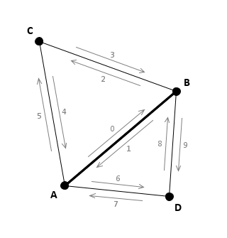
The following details will be relevant to our discussion of the Tinfour algorithms for constructing an AlphaShape from a Delaunay triangulation.
- Tinfour Delaunay triangulations implement a collection of vertices and edges. Triangles are not actively maintained in memory, but may be constructed on an as-needed basis.
- In the classic Delaunay triangulation, pairs of vertices are linked together by bi-directional edges. Tinfour uses an "edge-pair" structure in which two single-direction edges are coupled together, one edge for each direction of traversal.
- Each Tinfour edge carries a reference to a corresponding "dual" edge that supports the opposite direction of traversal. In the figure above, the edge labeled "0" indicates the traversal from vertex A to B. Its dual, the edge labeled "1" supports the traversal from vertex B to A.
- Tinfour assigns unique integer index values to each edge at the time it is created. These index values allow an application to maintain supplemental information about the edges they represent.
- To form triangles, each Tinfour edge is linked to two other edges. These linked edges are referred to the "forward" edge and the "reverse" edge. The Tinfour API provides methods for obtaining references to each linked edge (forward, reverse, and dual).
- When three edges are linked together to form a triangle, the triangle is always specified in counterclockwise order.
Additional details about the Tinfour edge concept are presented in our Wiki article Tutorial Using Edge Based Techniques.
Building an alpha shape
The Tinfour technique for building an alpha is a three-step process:
- Create a Delaunay triangulation from a set of scattered data points
- Use the alpha-circle criteria to identify edges from the triangulation as being either a border, or interior or exterior to the alpha shape (Edelsbrunner referred to exterior edges as α-exposed).
- Connect the border edges together to form polygons enclosing
the alpha shape.
- An alpha shape may consist of multiple polygons.
- Some polygons may include "holes" (nested polygons).
- For sufficiently small radius values, it may be impossible to build polygons that enclose all of the input points. Some points may remain as "orphans" which must be treated as isolated individuals rather than part of a polygon structure.
The Delaunay triangulation is the focus of the Tinfour software project. Given a set of scattered points, the Tinfour API includes classes that link points into a triangle-based mesh structure that can be accessed through the Java interface IIncrementalTin. Interested readers may consult our project documentation and Wiki page for more information.
Is an edge exposed?
Once a Delaunay triangulation is constructed from a set of scattered points, it may be passed to Tinfour's AlphaShape constructor along with an arbitrarily specified radius value.
AlphaShape begins by classifying each edge in the Delaunay triangulation as either interior (α-unexposed), exterior (α-exposed), or a border according to the following rules:
- α-exposed: If both of the alpha circles associated with the edge are empty, the edge is exterior to the alpha shape.
- α-unexposed: If both of the circles are occupied by distinct vertices, the edge is interior to the alpha shape.
- border: If one of the circles is occupied by one or more vertices and the other is empty, then the edge is a border of the alpha shape (see The circle selection criteria).
- border (Tinfour modified rule): If both circles are occupied by one or more vertices, but all enclosed vertices lie on the same side of the edge, then the edge is a border of the alpha shape (see Tinfour modifications for border identification).
If we had to search for every point in an input sample set in order to discover whether a circle is occupied or not, the processing cost for a large set of points might become prohibitive (on the order of N2). Fortunately, the nature of the Delaunay triangulation makes that unnecessary.
To determine the alpha exposure value for any standard edge in the Delaunay triangulation, it is sufficient to inspect the two vertices opposite that edge.[1] If an alpha circle is not occupied by either of the associated vertices, then it will not be occupied by any other vertices in the Delaunay triangulation. A typical edge/vertex situation is illustrated in the figure below
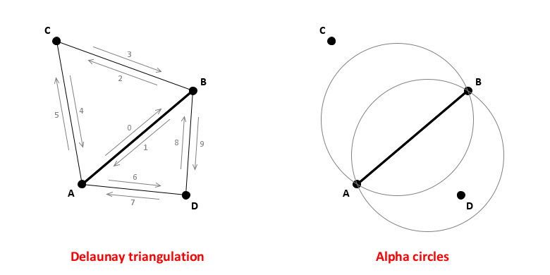
Classifying an edge as a border or interior component
When both alpha circles associated with an segment (pair of edges) are occupied by vertices, the segment is treated as being part of the interior of the alpha shape. When both circles are empty, the segment is treated as being exterior to the alpha shape. Because the alpha circles contain a vertex on one side of segment AB, but not both, the segment would be treated as a border. The alpha circle to the right of the edge is occupied by Vertex D. The alpha circle to the left is not occupied. Tinfour defines the side of the edge with an empty circle as being exterior to the alpha shape. The side of the edge with an occupied circle is treated as being in the interior.
During the construction of the AlphaShape, Tinfour maintains an array of flags indicating which edges are interior to the alpha shape and which are borders[2]. These arrays are named covered[] and border[]. The arrays are indexed using the edge index as shown in the figure above[3]. In the figure above, segment AB is a border because only one of the alpha circles is occupied (by vertex D). The segment has two sides (two Tinfour edge objects) which are numbered 0 and 1. In the figure, the edge to the left of segment, which has edge index 0, faces the exterior of the alpha shape. So border[0] would be set to true. The edge to the right of the segment, which has edge index 1, faces the interior of the alpha shape, so covered[0] would be set to true.
Stitching edges together to form alpha polygons
The alpha circle criterion allows an application to identify a set of edges that border an alpha shape. Once the border segments are established, the AlphaShape links them together into polygons using a sweep technique as illustrated in the figure below. Before considering the figure, we note the following:
- The outward side of the edge is marked with the border flag. For example, in the upper part of the image, edges 1, 15, and 21 are borders.
- The inward side of the edge is marked with the covered flag and treated as being interior to the alpha shape. For example, edges 0, 14, and 20 are covered.
- The alpha shape polygon will consist of the covered edges and be given in a counterclockwise order. In the figure, the alpha shape would be given by edges 20, 14, 0, 63, 60, etc.
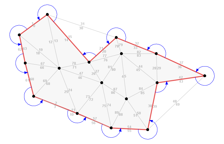
The sweep
The sweep process begins with an arbitrarily chosen border edge. As described above, the border edge faces outward from the alpha shape. The logic adds the dual of the border edge (the dual is the inner facing edge) to the polygon. The process then searches the edges that are adjacent to the border by sweeping in a counterclockwise order around its initial point (in the figure, the sweeps are shown as loops ending with arrows). The polygon is considered complete when the search reaches the starting polygon.
The alpha shape may contain multiple polygons. Once a polygon is completed, the code searches for any additional edges that have not yet been committed to a polygon. As they are found, the sweep-and-build process continues as described above. When no additional uncommitted edges are available, the polygon-building portion of the alpha shape algorithm terminates.
The final step in the process is to collect a list of any individual vertices that were not part of the region enclosed by the polygons. To do so, Tinfour simply checks for any vertices that were not connected to an edge that was classified as covered.
Accomplishing the sweep
To perform the sweep operation, the AlphaShape class uses the forward, dual, and reverse links for each edge. The figure below shows a locally concave section of the Delaunay triangulation near its upper corner.
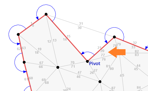
The choice of starting edge for the polygon building loop is arbitrary. Any border edge will do. For this example, we chose edge 21 as the starting edge of the polygon building loop. Its dual, edge 20, is interior to the alpha shape and would be marked as covered. The polygon building logic adds covered edges to the alpha-shape polygon and uses the border edges to navigate its perimeter. So once edge 20 is added to the polygon, the polygon building logic sweeps counterclockwise.
In the figure, we labeled the initial vertex of edge 21 the "Pivot". The next edge in the border traversal is edge 15. Recalling that Tinfour gives triangles in counterclockwise order, we see that edge 15 is the reverse link of edge 21. So for this particular layout (a locally concave section of the alpha shape), the transfer is simply a matter of moving to the reverse, edge 15. The building logic would add the dual of edge 15, edge 14, to the polygon and continue the sweep.
The figure below shows a section of a different Delaunay triangulation and illustrates a case where the alpha shape would be is locally convex. In that case, the traversal is a little more complicated. If the algorithm was positioned at edge 507 the sweep would have to traverse across four α-exposed edges in order to reach the next border segment (edge 501).
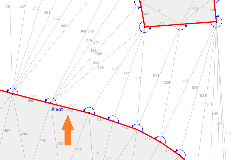
The observation that the traversal must sometimes cross multiple edges leads to a more complete description of the traversal rule:
- For the current edge, obtain its reverse link
- If the reverse link is a border, transfer to the reverse.
- If the reverse link is α-exposed, transfer to the dual of the the reverse link
Finally, we note that in the figures above, the sweeps sometimes pass outside the convex hull of the Delaunay triangulation. To ensure that the Delaunay triangulation link relationships are fully populated (reverse, forward, and dual), Tinfour implements a set of non-standard edges called "ghost edges". Ghost edges lie outside the convex hull and do not have a valid geometry. They are included in the Delaunay triangulation solely to provide a complete set of links. The presence of these edges allows the AlphaShape class to apply the traversal rules without special considerations.
Reclassifying edges based on neighboring triangles
Tinfour implements an additional modification to the original alpha shape logic by reclassifying some border edges based on the conditions of the triangle that it borders. While this idea is not original to Tinfour[4], it is often useful as a way of eliminating small holes and cavities from the alpha shape.
The figure below illustrates a case where the alpha shape is simplified by reclassifying edges
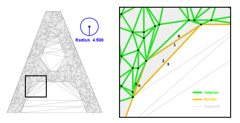
The gray filled areas in the image indicates Tinfour's interpretation of a modified alpha shape. The right panel shows a close up of the area in the letter A with edges color coded to show their classifications. Once again, we note that Tinfour edges have two sides. In the figure, some edges are labeled on either side with their edge index. Edges 0|1, 2|3, and 4|5 are border edges. Initially they are assigned covered and border flag values as shown in the table below.
| Side | Classification |
|---|---|
| 0 | Covered (interior-facing) |
| 1 | Border (exterior-facing) |
| 2 | Covered (interior-facing) |
| 3 | Border (exterior-facing) |
| 4 | Border (exterior-facing) |
| 5 | Covered (interior-facing) |
Based on the edge classifications, the stitch and sweep method described above would develop a triangle shaped hole from edges 1, 2, and 4 (using clockwise order because it is a hole feature). In fact, the unmodified edge classifications would result in a number of holes and cavities in the shape. But, as the table above shows, edge 2 was classified as covered because the vertex opposite the edge lies within its alpha circles. So edge 2 is an inward-facing side of edge 2|3, a situation which suggests that △1,2,4 should be treated as an interior triangle. This observation leads to the following rule:
If either the forward or reverse links of a border edge are classified as covered, the border edge should be reclassified as covered.
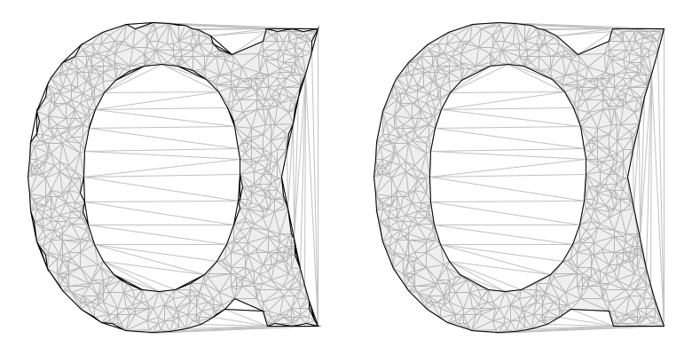
The figure below shows the effect of the reclassification rule. The panel on the left is based on an alpha shape constructed without the reclassification rule. The panel on the right shows an alpha shape constructed with edge-reclassification based on information from its facing triangle. The reclassification eliminates a number of hole and cavity features, resulting in a cleaner presentation.
The algorithm and the implementation
In the steps below, references "the edges in a Delaunay triangulation" refer to the standard (non-ghost) edges in the structure. That is, all edges the are enclosed within the convex hull of the triangulation. All such edges will have a valid geometry (vertices A and B in the images above), though in some cases the references to the opposite vertices (vertices C and D in the image above) will be null. For implementation purposes, the Tinfour edge iterator provides access to all the standard (non ghost) edges in a Delaunay triangulation as shown in the code snippet below:
    for (IQuadEdge edge : tin.edges()) {
       Vertex A = edge.getA(); // initial vertex of edge
       Vertex B = edge.getB(); // second vertex of edge
       Vertex C = edge.getForward().getB();         // vertex opposite edge, for triangle ABC
       Vertex D = edge.getForwardFromDual().getB(); // vertex opposite dual, for triangle BAD
    }
Step 1: Classify edges
Given a valid Delaunay triangulation and a specified alpha radius r:
- Obtain maximum edge index, maxEdgeAllocationIndex, allocate boolean arrays for covered[maxEdgeAllocationIndex] and border[maxAllocationIndex]. Arrays are initialized to value false.
- For each standard edge in triangulation
- If the edge is of length greater than or equal to 2×r, it is classified as α-exposed and no further work is required
- Get vertices A, B, C, and D as described above
- Construct pair of open circles with alpha radius r using A, B
- Test vertices C and D to see if they are within left and right circles;
if a vertex reference is null, it is treated as outside the circle.
- cInside0 = circle.isPointInCircleLeft(C)
- cInside1 = circle.isPointInCircleRight(C)
- dInside0 = circle.isPointInCircleLeft(D)
- dInside1 = circle.isPointInCircleRight(D)
- Using edge index eIndex for edge and dIndex for dual,
populate covered[] and border[] array elements as follows:
- A side of the edge is considered occupied if either or both of the alpha circles contains the vertex on that side.
- If both sides of the edge (the C side and the D side) are occupied, the edge is covered.
- If the left side (C side) is occupied and the right side (D side) is not occupied, then the left side is covered (covered[eIndex]=true) and the right side is a border (border[dIndex]=true).
- If the right side (D side) is occupied and the left side (C side) is not occupied, then the left side is a border (border[eIndex]=true) and the right side is covered (covered[dIndex]=true).
Step 1a: Reclassify edges based on neighboring triangles
The following logic reclassifies border edges to be non-border (purely covered) in cases where the facing triangle is interpreted as being interior to the alpha shape. This condition occurs when the two adjacent edges (the forward and reverse) edges are both marked as non-border and covered.
- For all edges (both sides) in the triangulation, perform
the following steps:
- If the edge is a border, obtain its forward and reverse edges. These edges represent the three edges of a triangle
- If the reverse and forward edges are covered and not borders, then mark the current edge as covered and not a border.
Step 2: Assemble alpha polygons
The Tinfour edge iterator loops through pairs of edges. So in the outline below, there is a test to see whether either an edge, or its dual, is a border. Because the main loop iterates through all polygons in the triangulation, it maintains an array called "visited" to keep track of which edges are added to an alpha polygon. This array is used to prevent edges from being processed more than one.
- Allocate an array visited[maxEdgeAllocationIndex] and initialize it to value false to indicate when edges are processed
- Find a starting edge for a polygon. For each edge-pair in
the Delaunay triangulation:
- If the visited array indicates that the edge-pair has already been processed. Continue to the next edge-pair in the iteration.
- If the base edge of the edge-pair is a border, then assign it as the starting edge
- If the dual edge of the edge-pair is a border, then assign it as the starting edge
- If neither side of the edge-pair is a unprocessed border, continue to the next edge-pair in the iteration.
- Initialize a new polygon.
- Set a traversal edge reference, e, to the starting edge: e=starting edge
- The polygon-build loop: Repeat the following steps:
- If the edge is a border or a covered edge:
- Mark the e as visited and e.getDual() as visited (i.e. both sides of the edge are marked as visited).
- Add the dual of the edge to the polygon
- Advance the traversal edge, e, to the next edge in the sweep by setting e=e.getReverse()
- If the edge is uncovered:
- Advance the traversal edge, e, to the next edge in the sweep by setting e=e.getDual().getReverse(). This action effectively skips over the uncovered edge
- The polygon-build loop terminates when e equals the starting edge.
- If the edge is a border or a covered edge:
Step 3: Collect orphan vertices
The assemble polygons step will have set visited flags for any edge that was identified as being part of the alpha shape. If the alpha radius is sufficiently small, there may exist additional vertices in the Delaunay triangulation that were not associated with an incorporated edge. Add these vertices to a list of unassociated vertices.
- For each edge-pair in the Delaunay triangulation that is
not covered, not a border, and not visited, perform
the following for both the base side of the edge and its dual:
- Determine whether the initial vertex connects to an
edge that is covered or that has already been processed.
If not, perform the following:
- Set a flag called uncommitted to true.
- Loop on each edge that starts with vertex
A (in Tinfour, this action is accomplished
using the "pinwheel" iterator).
- If the loop-edge is covered, a border, or visited, set uncommitted to false
- Mark the loop-edge as visited.
- If the uncommitted flag is true, then the starting vertex for the edge is an unassociated vertex. Add it to the collection of unassociated vertices
- Determine whether the initial vertex connects to an
edge that is covered or that has already been processed.
If not, perform the following:
Note that in the description above, the inner loop only sets the visited flag for one side of the edges. So, if the logic is processing the edge AB, the first time the inner loop executes (for the edge), only the sides of the edges directed away from point A are marked as visited. Then, as it processed the dual, BA, the sides of the edges directed away from point B will be marked as visited. This approach ensures that both endpoints for an uncovered edge are correctly processed and that no vertex is added to the unassociated vertices collection more than once.
Conclusion
The Tinfour AlphaShape class provides a modified version of the classic 2D alpha shape technique that reduces the incidence of hole and cavity features. These notes provides implementation details and an outline of the steps performed by AlphaShape. The next article in this series provides a derivation of the alpha circle calculation.
Future work
We have not yet established a rigorous mathematical proof for one of the key assumptions in the Tinfour modification. The logic assumes that it is sufficient to establish whether an edge is α-exposed by examining just the two vertices opposite an edge (see Is an edge exposed? above. During the investigation, the Tinfour developers performed extensive testing that supported this idea, but without a formal proof, we cannot be sure that there are not cases for which the assumption is inadequate. Further investigation is required.
An example application using the Tinfour alpha-shape API
Finally, the illustrations included in this article were created using applications built on top of the Tinfour software library. Tinfour includes an example application, AlphaShapeDemoImage.java, which demonstrates many of the techniques used for these illustrations.
Notes
[1] We have not yet established a rigorous mathematical proof that it is sufficient to establish whether an edge is α-exposed by examining just the two vertices opposite an edge. Additional investigation is required.
[2] Edelsbrunner, et al., original paper treats border edges as α-exposed. That choice reflects the mathematical basis for their proofs and derivation (as does the choice of open circles versus closed circles for the edge selection criterion). To distinguish implementation considerations the Tinfour code does not use the term "unexposed". Instead, it uses the term "covered" to refer to edges that are either α-unexposed (interior) or part of the border.
[3] For clarity, it is worth noting that what Tinfour calls an "edge" is usually just a single side of a bidirectional segment created between two vertices in the Delaunay triangulation.
[4] Tinfour's edge reclassification technique was suggested, in part, by an example provided on the stackoverflow website at https://stackoverflow.com/a/23073229/12664668.
References
Edelsbrunner, Herbert; Kirkpatrick, David G.; Seidel, Raimund. (1983). On the shape of a set of points in the plane, IEEE Transactions on Information Theory, 29 (4): 551–559, doi:10.1109/TIT.1983.1056714.
Fischer, K. (2000). Introduction to alpha shapes. Stanford Computer Graphics, Stanford University. Accessed July 2025 from https://graphics.stanford.edu/courses/cs268-11-spring/handouts/AlphaShapes/as_fisher.pdf